Introduction to LiDAR technology
Anh Vũ Võ
Center for Urban Science and Progress
New York University
April 2019
Outline
- Week 1
- LiDAR technology
- Brief introduction of CloudCompare and PDAL - Preparation for Week 2
- Terrestrial LiDAR scanning demonstration
- Week 2
- LiDAR data
- LiDAR data visualization
and processing with CloudCompare - LiDAR data processing with PDAL
Safety
- Riegl VZ-2000i: Laser Class 1 (Eye Safe)
- Garmin LiDAR Lite v3HP: Laser Class 1 (Eye Safe)
- Do not stare at the lenses at close range during operation!
- Do not hit the scanner's tripod!
Notre Dame de Paris was engulfed in fire on Apr 14, 2019
LiDAR scans may be of great use for the cathedral's restoration
LiDAR technology - an introductory overview
Definition
- The word “LiDAR” is an acronym for Light Detection and Ranging.
- LiDAR is an active sensing technology that use light (most commonly from a laser) to measure range/distance.
- Today, LiDAR is often used for 3D data capture.
- LiDAR works across various scales: small object capture, indoor mapping, topographic mapping.
- Other acronyms: lidar, LIDAR, LADAR
Sample data
Mexico Unprovenanced wall panel (58 cm)
Sample data
370 Jay St., Brooklyn
Sample data
2015 Dublin LiDAR scan
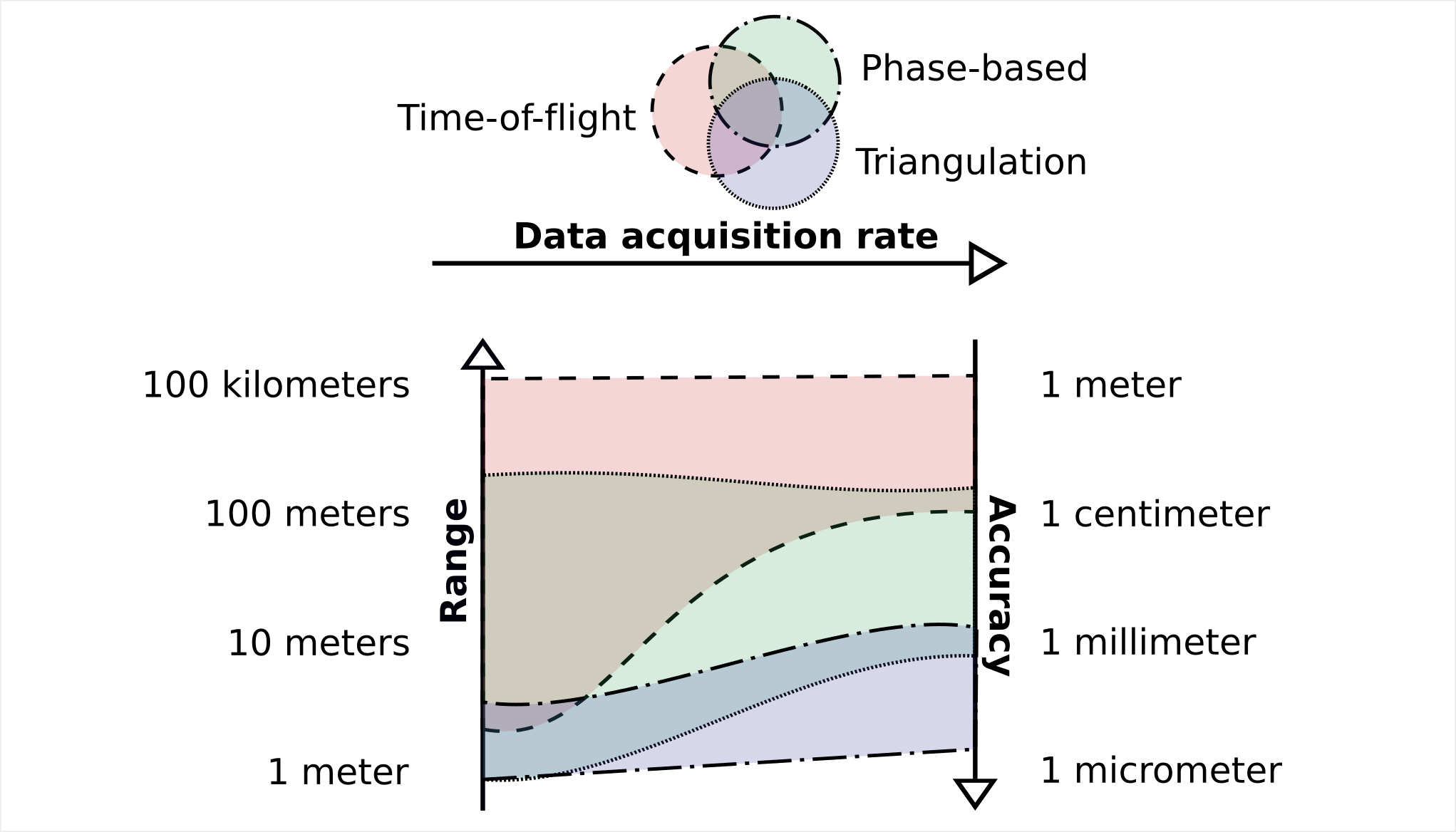
Ranging priciples
- Time-of-flight measurement
- Phase-based measurement
- Triangulation
Time-of-flight measurement

Time-of-flight measurement
(Also known as pulsed LiDAR)
- A TOF LiDAR ranger consists of a laser emitter and a photoelectric receiver. The emitter send out a very short but intense laser pulse. The pulse travels from the ranger to the object being measured and returns to the receiver after being reflected from the object. The time elapsed between the pulse emitted and its reflection is precisely measured. The range value is derived based on the measured time interval and the known speed of light
Time-of-flight measurement
- TOF LiDAR is suitable for both short- and long-range applications (from several meters in terrestrial applications to hundreds of kilometers in space borne applications).
- LiDAR accuracy decreases with the increase in the ranging distance. TOF LiDAR can be as accurate as a few milimeters at an under 100m range.
- Pulse repetition frequency (PRF) can exceed 1 MHz.
| Riegl VZ-2000i (terrestrial) | Riegl VQ-780i (airborne) | |
|---|---|---|
| Max. range | 150m - 2,500m | 300m - 7,500m |
| Accuracy | 5mm @ 100m range* | 20mm @ 250m range* |
| PRF | 1.2 MHz | 1.0 MHz |
Phase-based measurement
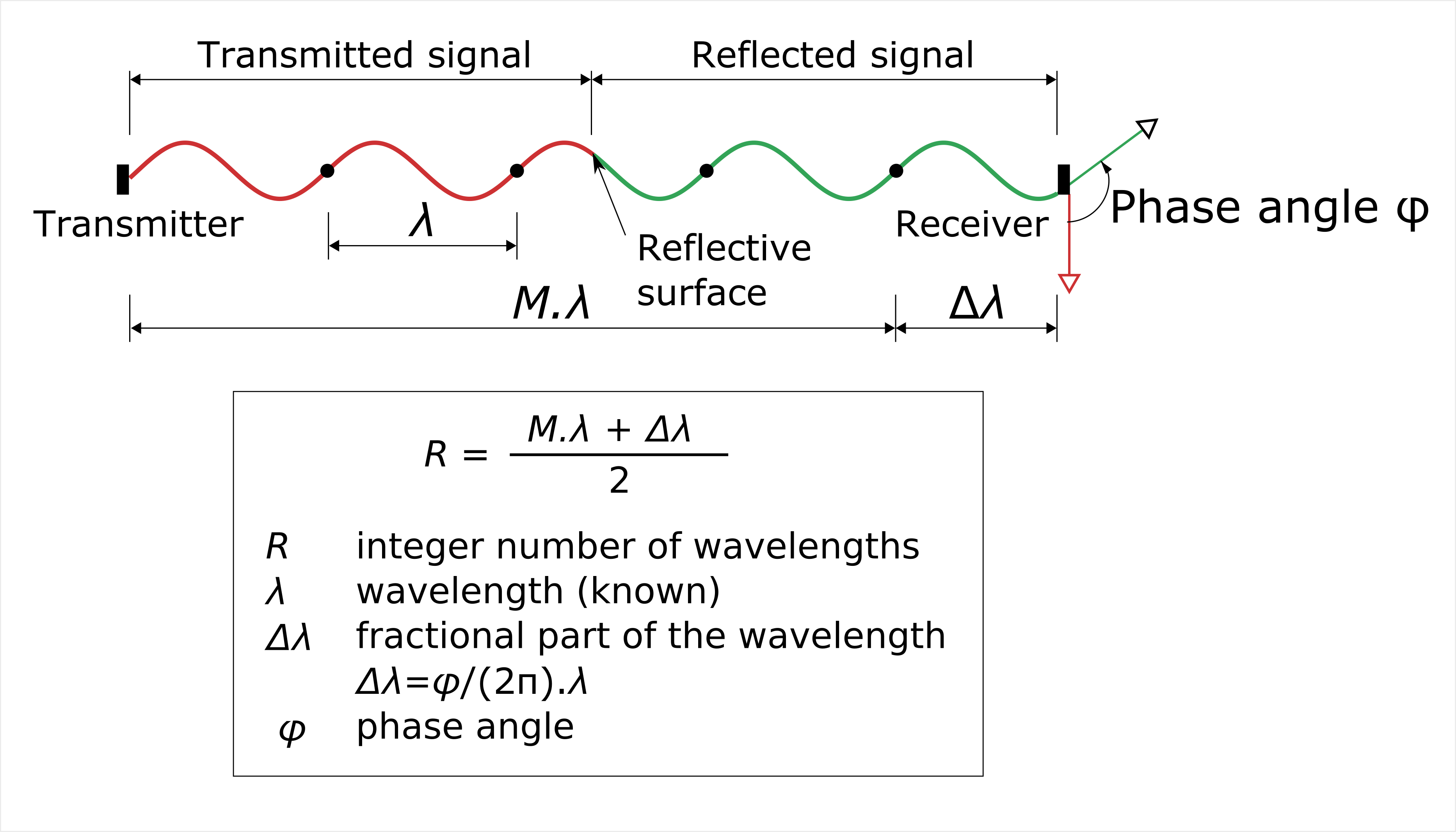
Phase-based measurement
(Also known as continuous wave LiDAR)
- A phase based ranger transmits a continuous beam of modulated laser radiation. The range value is partially derived based on the phase difference between the emitted and received sinusoidal signals. The integer number of wavelengths is determined by a separate process called ambiguity resolution.
Compared to TOF:
- Due to the high power demand, phase-based LiDAR is less suitable for long range applications. Ranging capability is typically restricted to under 100m.
- Higher data acquisition speed (eg. Blackmore AFDL reaches 2.4 MHz).
- Higher ranging accuracy (eg. Faro Focus S350 can reach 1mm @ 25m).
Triangulation
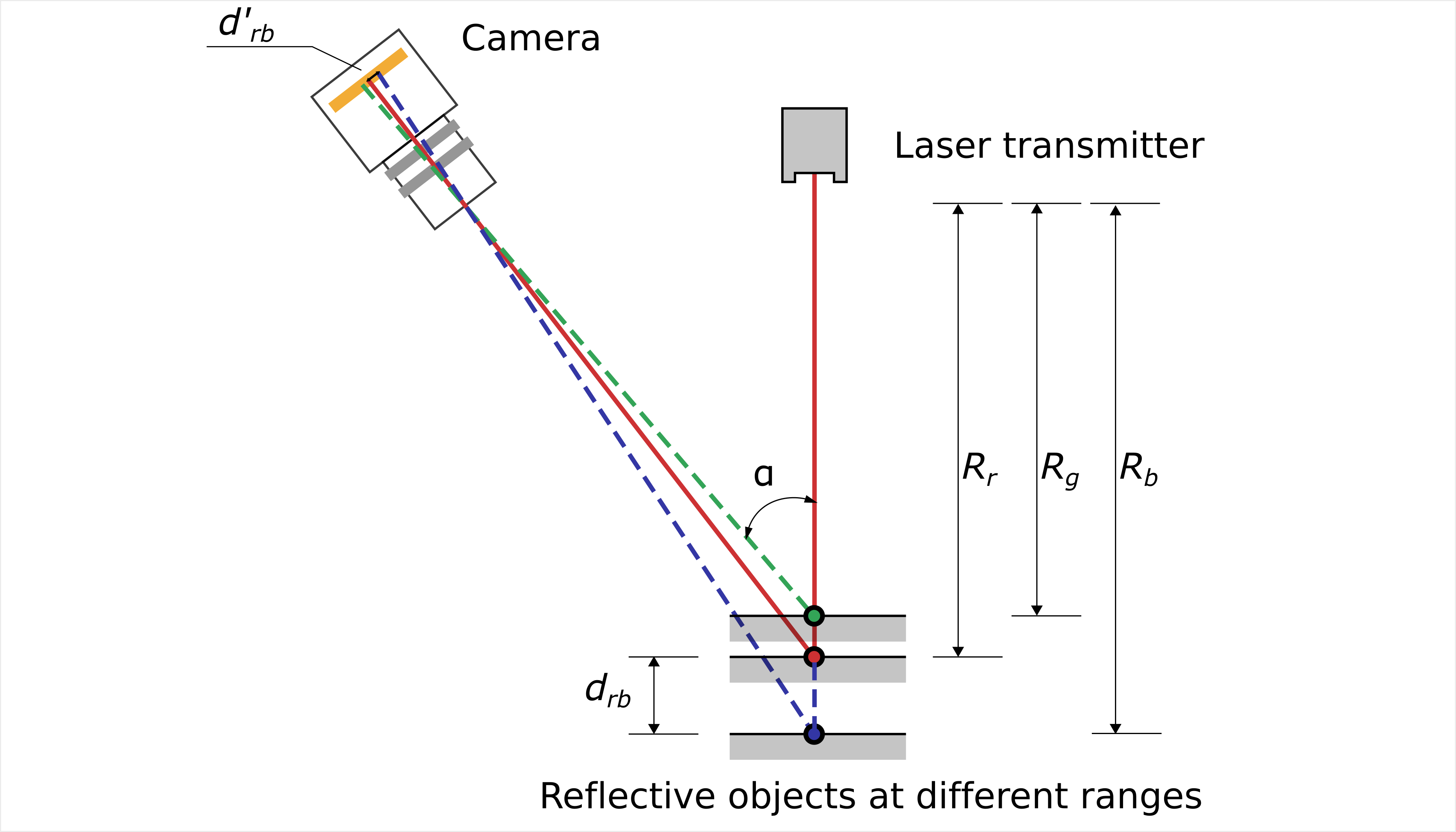
Triangulation
- A laser triangulation device has a laser emitter and a camera, aiming at the inspection target at 2 different angles. Range is derived based on trigonometry with the known angular offset between the laser emitter and the camera.
- Triangulation-based LiDAR has limitted range (i.e. a few meters maximum) but high accuracy (in the order of tens of micrometers) and high data acquisition rate.
Ranging principles - Summary
Ranging - Demo
Static LiDAR profiling and mapping
Profiling
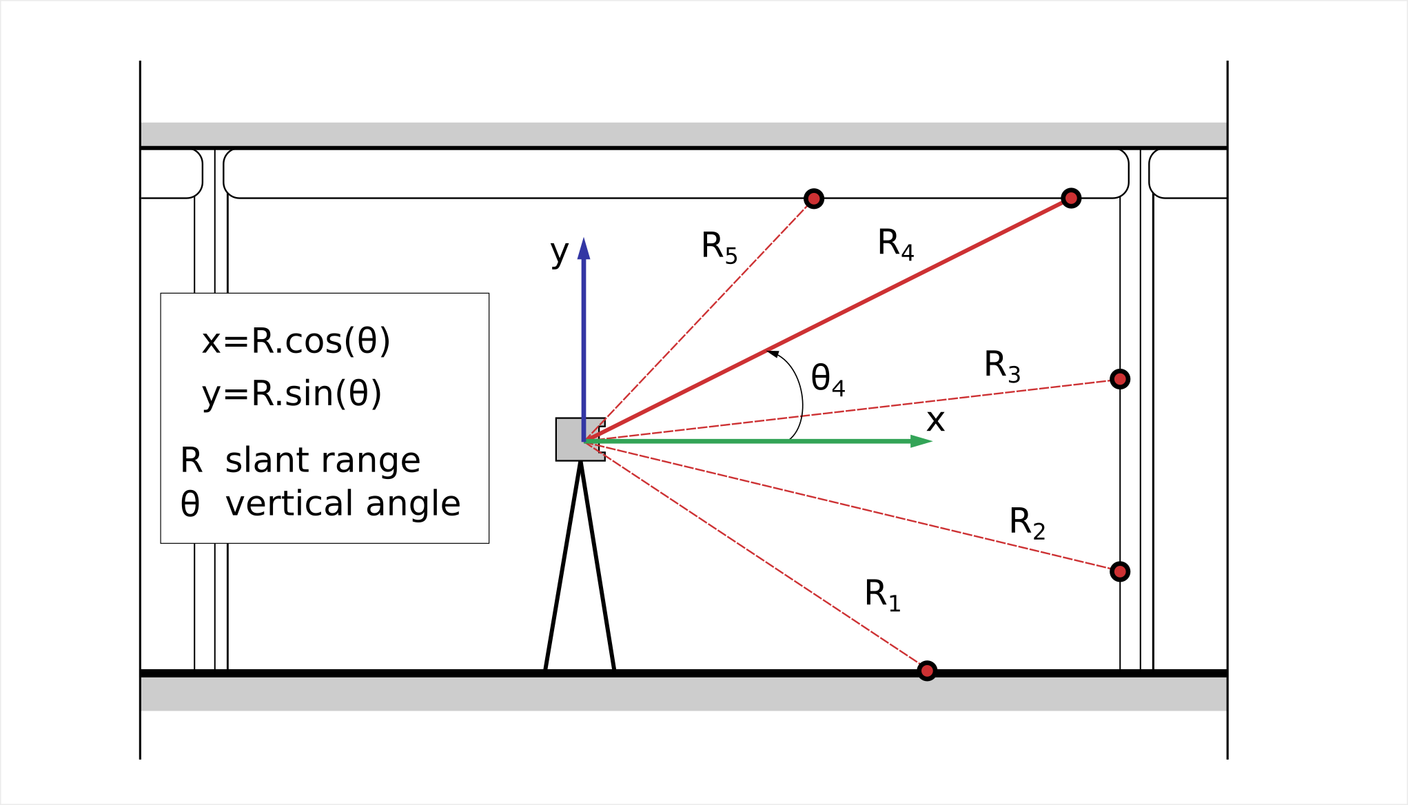
Profiling
- Incrementally sweep the laser beam up and/or down in a vertical plane.
- At each step, measure the vertical angle (θ) and the slant range (R). Each tuple (θ, R) defines a point in the 2D sweeping plane.
- (θ, R) defines a 2D point in the polar coordinate system originating at the system's rotating center. (θ, R) can be transformed to a Cartesian coordinate system [e.g. (x, y)].
Profiling - Demo
Mapping
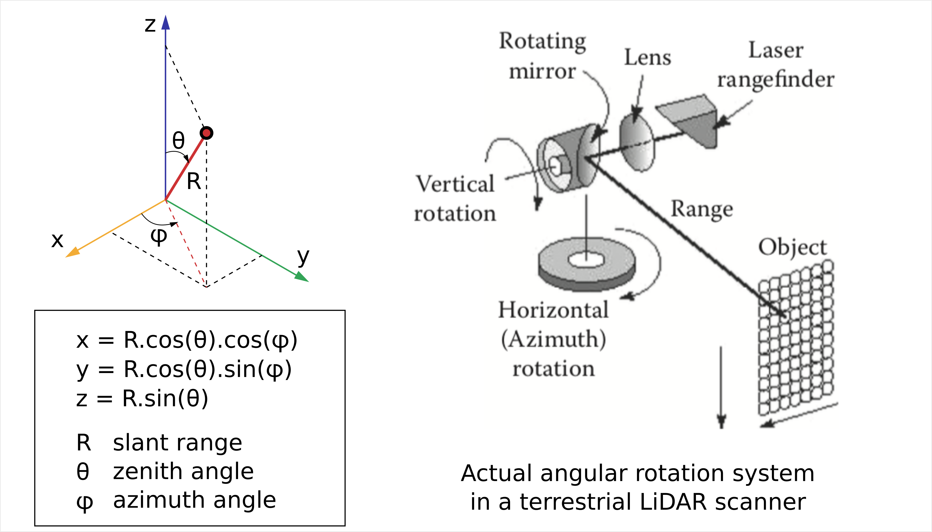
Figure excerpt from (Shan and Toth 2018) Chapter 2
Mapping
- Increase both the horizontal angle (aka azimuth, φ) and the vertical angle (aka zenith θ) stepwise and measure the LiDAR range value (R).
- Each triplet (R, θ, φ) defines a point in the 3D space originating at the system's rotating center. The coordinates can be transformed to a Cartesian coordinate system.
- In practice, the laser transmitter and receiver are often kept stationary. Rotations are performed by a rotating mirror mechanism.
Latency in systems based on mechanical scanning
Solid-state LiDAR mapping
(Optional reading)
- Mechanical scanning is subjected to latency.
- 3D mapping can be achived without a scanning mechanism. Example technologies include 3D flash imaging LiDAR, and multilayer laser scanners.
- Each data frame captured by a solid-state LiDAR is synonymous. 3D flash LiDAR can produce 3D video.
Flash LiDAR - Section 2.5 ASPRS's Manual Section 3.6.3.2 (Shan and Toth, 2018)
Kinematic LiDAR mapping
(LiDAR mapping from moving platforms)
- Scanning mechanisms
- Integration with a positioning and orientation system (POS)
Scanning mechanisms
- Unlike static LiDAR mapping systems, which require motions in 2 dimensions to cover a 3D scene, kinematic LiDAR mapping needs only 1 motion as the platform movement already covers 1 dimension.
- 3 main scanning patterns:
- Oscilatting plane mirror
- Continous rotating polygonal mirror
- Nutating mirror prism (aka Palmer scan)
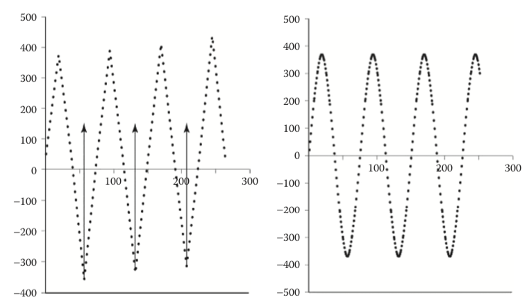
Oscilatting plane mirror
- Results in saw-tooth or sinusoidal pattern
- Lower uniformity in point distribution
- Contain high noise at the edge of the scan lines due to high mirror accelation
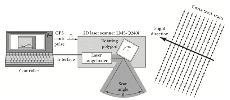
Continous rotating polygonal mirror
- Results in parallel scan lines
- Highly uniform point distribution
- No high mirror acceleration as in the case of oscilating mirror
- Low rate of returning pulses
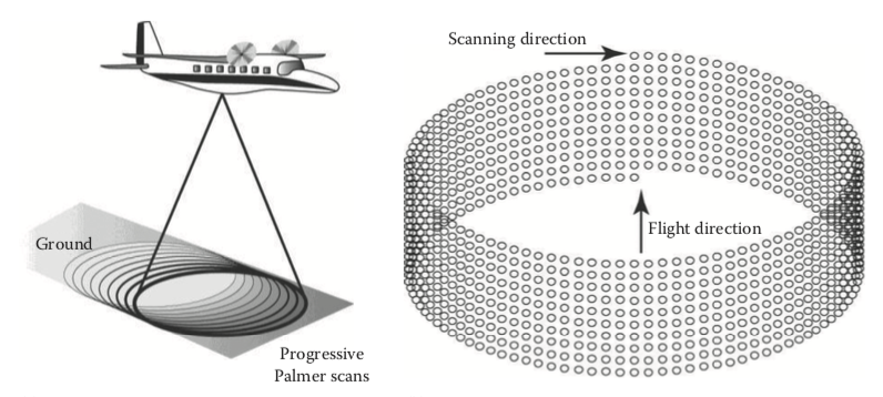
Palmer scanner
- Results in elipsoidal scan lines
- Relatively uniform point distribution
- No high mirror acceleration as in the case of oscilating mirror
- High rate of returning pulses
- Limitted angle of incident
Integration with a positioning and orientation system (POS)
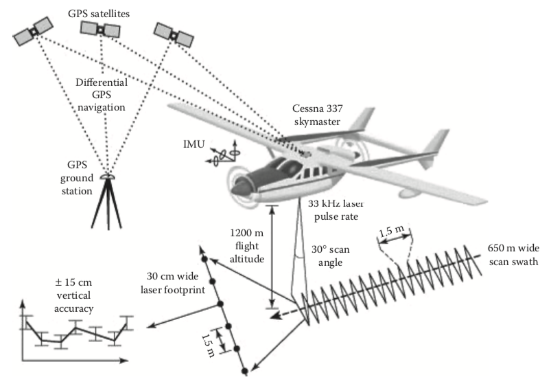
- Raw ranging and angular data are collected within the sensor's internal coordinate system, which is in motion.
- The process of registering the raw data into a fixed, ground system of geographic coordinates is called georeferencing.
- Georefencing requires knowledge of the position and orientation of the moving platform, which is obtained from the POS.
Integration with a positioning and orientation system (POS)
- A POS comprises a GNSS (global navigation satellite system) receiver (typically a GPS) and an IMU (inertial measurement unit).
- By referencing to ground stations, an onboard GPS can position the platform up to an accuracy of 5 to 10 cm under good conditions. However, GPS readings are only available at 1 to 10 Hz.
- An IMU is composed of several accelerometers and gyroscopes, which deliver linear acceleration and angular rate data at 0.2 to 2 kHz.
- IMU plays 2 roles:
- Fill in the positional data when GPS signal is not available.
- Provide orientation data.
Integration with a positioning and orientation system (POS)
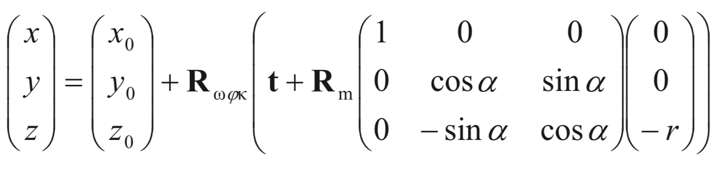
| (x0, y0, z0) | GPS antenna's position |
| r | range |
| α | scan angle |
| Rωφκ | rotation angles |
| t | GPS antenna offset |
| Rm | IMU misalignment |
Preparation for Week 2
- CloudCompare: open source C++ GUI software for point cloud visualization and processing
- PDAL (Point Data Abstraction Library): open source C/C++ library with Python binding for point cloud I/O and translation
- Sample datasets
- Demo - NYC Post Sandy LiDAR data extraction, translation, and visualization